Network Level Structural Evaluation

Prepared by Magdy Mikhail, Texas Department of Transportation

Network-level structural data provides information about the load-carrying capacity of the pavement network. It describes base and surface strength, as well as subgrade strength. This information can be essential in determining whether a candidate project needs sub-surface rehabilitation or if a less expensive (surface) preventive maintenance treatment can be used instead.  The data can also be used for evaluating routes for super heavy loads.

Network level structural evaluation can be done using one of the available devices below:

  • The Falling Weight Deflectometer (FWD) to assess structural capacity of pavements, data is collected every 0.3-0.5 miles by applying an impact load of 9,000 lb to simulate the  load of one tire of a single axle loaded to 18,000 lb. the deflection basin generated is suitable for structural evaluation.  The data is collected at a relatively slow rate and traffic control is always needed for the safety of the operator, equipment and travelling public.
  • Rolling Wheel Deflectometer (RWD) device that uses two sensors to collect the maximum pavement surface deflection under an 18-kip single axle semi-trailer load traveling at normal highway speeds. The device provides high production suitable for network level evaluation and traffic control is not needed for data collection.
  • Traffic Speed Deflectometer (TSD) which is a truck trailer combination having a 10 tonnes single axle with dual wheels. The movement of the pavement surface caused by the axle load is measured with four (or more) laser sensors and is transformed to simulate a deflection basin.  The equipment operates at highway speed without the need for traffic control.


Continuous Deflection DevicesContinuous deflection testing devices at MnROAD test facility for an FHWA study on “Network Level Pavement Structural Evaluation”. From left to right: Greenwood TSD, Euroconsult Curviameter, and Applied Research Associates (ARA) RWD. [Picture Source: “Network Level Pavement Structural Evaluations – A Way forward,” Presented by Nadarajah Sivaneswaran (FHWA) at National Pavement Evaluation Conference 2014]

In general the data from the different equipment can be incorporated into a structural index to be used in the decision tree to generate preventive maintenance and rehabilitation plans and optimize the use of the available funds.


For more information, please contact Magdy Mikhail at: Magdy.Mikhail@txdot.gov

Pavement Preservation as a Network Maintenance Strategy

Prepared by Raja Shekharan, Virginia Department of Transportation

Maintenance of pavement network in an optimal condition has been increasingly becoming a necessity for various agencies. Individual pavement sections within a network are at different condition levels and require several different types of appropriate Maintenance and Rehabilitation (M&R) treatments. If the availability of funding for the maintenance of the network is not a concern, plausibly every pavement section needing a treatment could be provided with the treatment. In reality, there is rarely enough funding to cover the maintenance needs of an entire network, and most of the times the available funding can sufficiently address only a portion of the M&R needs of a network.

To use the limited funds in a cost-effective manner, various types of strategies and analysis procedures are adopted. As a strategy for network maintenance, a mix of fixes that includes pavement preservation, i.e., a spectrum of treatments ranging from lighter types such as preventive maintenance to heavier types such as reconstruction is adopted. Pavement preservation represents a proactive approach in maintaining pavements that reduces expensive heavier treatments and associated traffic disruptions while providing increased mobility and reduced congestion. Based on the existing structural and functional condition of pavements, there are windows of opportunity when particular types of treatments would be suitable. Established pavement management systems answer the questions of when, where, and what regarding the treatment types to be provided for various pavement sections. This makes it all the more important to not just address the worst sections but to use mix-of-fixes as a network level maintenance strategy. The lighter preventive type of treatments can be provided to those sections that are lightly distressed and require only functional conditions to be addressed while the heavier treatment types are to be provided for pavements that are heavily distressed requiring some kind of structural condition to be addressed. The lighter types of treatments are more economical on per unit basis and therefore can cover a larger portion of the network with a given amount of funding or a portion of that funding. Application of these lighter treatments to appropriate sections retards their deterioration into condition states needing costlier heavier treatments.

Heavier treatments are necessary to address heavily distressed pavements that cannot be properly addressed with lighter treatments. With a given funding level it may not be possible to address all the pavements in the network that need heavier treatments within one year. These sections need to be addressed over multiple years while other sections are provided with other appropriate treatments as a part of the network maintenance strategy. It is well recognized that using treatments as band-aids, wherein a lighter treatment is used as a temporary measure till the needed heavier treatment is applied, is not a part of pavement preservation strategy. It is also to be noted that providing heavier treatments are not cost-effective on sections requiring lighter treatments. On the other hand, providing lighter treatments are ineffective for sections when heavier treatments are warranted. This leads to a reemphasis of providing the right treatment to the right section at the right time for the optimal maintenance of a pavement network.

This article originally appeared in the International Journal of Pavement Research and Technology (IJPRT), Vol. 8, No. 1 issue, 2015. For more information, please contact Raja Shekharan at: Raja.Shekharan@VDOT.Virginia.gov

H-Chart: A Visualization Tool for Pavement Project Review

Prepared by Zhongren Wang, Caltrans

1. Introduction

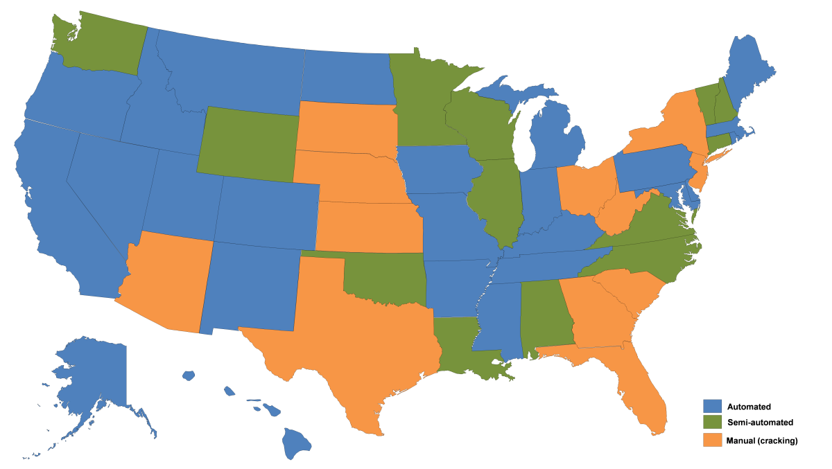
A typical output from a Pavement Management System (PMS) is a list of recommended pavement improvement projects. These PMS-recommended projects need to be reviewed, adjusted, and finalized before possible funding commitment. In the review process, the relationships between the recommended projects and the currently programmed, under-construction, and as-built projects must be identified and closely examined to avoid gaps, overlaps, or inappropriate treatments. Presented in a tabular format, such a list of projects does not lend itself to easy identification of the necessary relationships. A visualization environment is necessary.

At the California Department of Transportation (Caltrans), the importance of such a visualization environment for project review has long been recognized. In the past, Caltrans pavement engineers manually drew horizontal bar charts using Microsoft Excel® for such purposes. Led by Tom Pyle, a Caltrans Supervising Transportation Engineer, the manually-drawn bar charts were further developed and automated in the process of implementing the Caltrans pavement management system, called PaveM. Present automation was developed through contract with the University of California Pavement Research Center (UCPRC). The product is called H-Chart, short for Highway chart. The following is a brief description of the H-chart.


2. H-Chart

An H-chart, as shown in Figure 1, provides the visualization of all past, current, and future projects for one direction of a specific route within one county, and one district. Caltrans divides its jurisdiction into 12 districts up and down California. For example, the H-chart shown in Figure 1 is dedicated for the northbound direction of route 101 in Del Norte County, in Caltrans District 01.

In Figure 1, the x-axis shows the county odometer and the y-axis shows Year. Projects are shown as hatched and colored horizontal bars. The project limits (the start and end locations) are located on the x-axis by means of county odometer values. These county odometer values are computed from the state odometer associated with the start and end of a project. The year of the project is indicated by its vertical location on the chart.

An H-chart displays projects with four different states, namely (1) Completed or as-built, (2) Under Construction, (3) Programmed, and (4) PMS- or PaveM-Recommended. These project states are indicated in the chart by different cross-hatching patterns. In an H-chart, the earliest known as-built projects are displayed at the bottom of page, followed by the programmed and under construction projects, and finally the recommended future projects at the top. The thick dashed horizontal line in Figure 1 separates the recommended future projects from the rest.

Each project shown in Figure 1 is also identified by a budget group. There are four budget groups for typical pavement projects in Caltrans. These include (1) Highway Maintenance (HM) Preventive, (2) HM Corrective programs, (3) Capital Program Maintenance (CAPM), and Rehabilitation. Each budget group is associated with a specific color. For example, Rehabilitation group is associated with red color.

Each project also has a label that contains such information as: treatment type, lane number or “All”, Expenditure Authorization (EA) number and Post-Mile (PM) limits.  The contents of the label are configurable when the H-charts are generated. Use the label in the upper left corner of Figure 1 “CinPlePrecyc-All 01-2T12LA-T-II” as an example, this label signifies that this particular project is a PaveM-recommended project with a Cold-in-Place-Recycling treatment for “All” lanes. The EA number of 01-2T12LAT is a temporary one (for future potential project with no funding commitment), because it ends with a capital letter ‘T’. As a rule, an EA number with funding commitment ends with a numeric value in Caltrans. For example, the label shown in Figure 1 “Med OL-All 01-49940” means a “Medium Overlay” treatment for all lanes with an EA number of “01-49940”. The “-II” following the EA number refers to the PaveM running Scenario that corresponds to the title of the chart.

Together with the depicted projects, pavement type and pavement condition information is also respectively shown at the top and bottom of the sample H-chart shown in Figure 1. The cracking and IRI values are based on the latest available pavement condition survey. The label for ‘crack%’, such as “0.3/2:0.7” shown at the lower left corner of Figure 1 means that the average wheel path cracking across all lanes from PM 0 to PM 4.4 is 0.3%, and the highest cracking percentage is 0.7%, occurring in lane number 2.

H-Charts are generated automatically with minimal post-processing in Excel®. A total of 1066 H-charts can be generated across the entire California pavement network based on the available district, county, route, and route direction combinations. The detailed breakdowns of these H-charts for each Caltrans district are tabulated in Table 1. Readers are encouraged to try out this web-based H-Chart generation application on their own. The website is: http://dev.ucprc.ucdavis.edu/PaveM-rViewer/.


Table 1. The Number of H-Charts for Each District and the State

District 1 2 3 4 5 6 7 8 9 10 11 12
Number 60 80 132 175 84 120 98 88 38 99 56 36
Total 1066


zwang_fig1

Figure 1 A Sample H-Chart (Please click on figure to see larger version)


3. How to Use an H-Chart?

With pavement condition, as-built projects, programmed projects, and PaveM-recommended projects visualized in one chart, an H-chart provides an effective working environment for pavement engineers to evaluate, compare, adjust, and select projects for future programming and planning purposes. An H-chart makes it easy to identify overlapping projects in schedule, or in limits. For example, project 01-49940 and 01-08080 shown in Figure 1 overlap in schedule. It may not make sense to apply a medium overlay treatment on top of a thin overlay treatment that just applied a year ago. An H-chart also facilitates the easy identification of project gaps. For example, the segment from PM 20 to 25 has not been treated ever since the year of 1994. Why is there such a long hiatus for a flexible pavement to be treated? Is it because of too low a traffic volume?  Is it due to short of funding? Or is it because the project history is not completely shown by the H-chart? Answers to these types of questions may well help better plan for the current and future projects.

In addition, an H-chart may help better justify a project by showing pavement condition and the proposed projects simultaneously. The H-chart shown in Figure 1 may be carried to the field to help adjust project limits on the scene; or to a project public hearing meeting to make project briefing and public education more effective.


4. Summary

As a visualization tool for project review, H-charts greatly facilitate the project selection process. It is a powerful working environment to identify project gaps, overlaps, and justify candidate projects and adjust/select potential projects. It can be used in office, or in the field. It is also instrumental for management briefing or public education purposes. It is a great feature for a PMS to possess to better support the decision making process for pavement project selection.


For more information, please contact Zhongren Wang at: Zhongren.Wang@dot.ca.gov

Basic Data Terminology

Prepared by Dr. Nasir Gharaibeh, Texas A&M University

It’s been said that data is the fuel that makes pavement management systems run.  Data terminology can be confusing because some terms can be defined in different ways.  Here are definitions of 10 basic data-related terms.  I hope you find this post helpful.

  • Data quality:  The principal dimensions of data quality are accuracy (closeness between a data value and the real-world value that it represents), completeness (absence/presence of missing values – a value that exists in the real world but is not in the database), and timeliness (how current the data are for the task at hand).  (1)
  • Data mining: The process of discovering interesting patterns from data.  As a knowledge discovery process, it involves in-depth analysis such as data classification, clustering, outlier/anomaly detection, and the characterization of changes in data over time. (4)
  • Data warehouse: A repository for long-term storage of data from multiple sources, organized so as to facilitate management decision making. The data are stored under a unified schema.  Data warehouse systems provide data cleaning, data integration, and online analytical processing (OLAP). (4)

600px-Applications-database.svg

  • Data Mart:  A subset of a data warehouse that supports the requirements of a particular business function.  It is a scaled-down version of a data warehouse. (2)
  • Data schema: A logical schema describes the design (blue print) of the database.  A physical schema is the collection of actual tables (and other objects) that the database is comprised of.
  • Index: A commonly used method for rapidly retrieving specified rows from a table without having to search the entire table.  Each table can have one or more indexes specified. Each index applies to a particular column or set of columns. For each value of the column(s), the index lists the location(s) of the row(s) in which that value can be found. (3)

600px-Suitcase_icon_blue_green_red_dynamic_v32.svg

  • Legacy data: Data collected by an information system that has been replaced by a newer system, and which cannot be immediately integrated into the newer system’s database. (2)
  • Metadata: The data that describes data. For example, a data point may consist of the number, “ 150. ” The metadata for that data may be the words “ Weight, in pounds.” (2)
  • Relational Database: A collection of tables, each of which is assigned a unique name.  Each table consists of a set of attributes (columns) and usually stores a large set of tuples (records or rows).  Each tuple in a relational table represents an objects identified by a unique key and described by a set of attribute values. (4)
  • Structured Query Language (SQL) (pronounced sequel): A computer language used to retrieve data from a relational database. (3)

Sql_database_shortcut_icon

References:

  1. Data quality: concepts, methodologies and techniques, by Carlo Batini, and Monica Scannapieca. Springer, 2006.
  2. Repurposing Legacy Data : Innovative Case Studies, by Jules J. Berman, Computer Science Reviews and Trends, Elsevier Science, 2015.
  3. Database design : know it all, by Toby Teorey et al., 2008.
  4. Data Mining Concepts and Techniques, by Jiawei Han, Micheline Kamber, and  Jian Pei, 3rd Edition, Elsevier Inc., 2012.


For more information, please contact Nasir Gharaibeh at: ngharaibeh@civil.tamu.edu

A Summary of Highway Agency Pavement Condition Data Collection Practices

By Linda Pierce, Applied Pavement Technology, Inc.

Over the last 16 months, I’ve had the pleasure of conducting (along with Katie Zimmerman, Applied Pavement Technology, Inc., and Luis Rodriguez, FHWA) FHWA workshops for Quality Management Procedures for Network Level Pavement Condition.  To date, five workshops have been conducted in North Carolina (pilot), Maryland, Tennessee, Washington State, and Kansas, and have been attended by 30 state highway agencies, FHWA representatives, and two local agencies.  The workshops have provide an opportunity for agencies to obtain and share information related to pavement condition data collection and quality management activities.

The following provides a summary of the more common pavement condition data collection practices.  Note―some of the following information has been obtained from other sources.

Figure 1 represents the type of equipment/process (automated, semi-automated, or manual/windshield) used for collecting pavement surface distress (i.e., cracking).  All agencies reported that the International Roughness Index (IRI), faulting, and rutting data is collected using automated equipment.  The majority of agencies (twenty-six) conduct data collection using fully automated surveys, thirteen agencies use semi-automated surveys, and twelve agencies conduct windshield surveys.  Many of the agencies that currently collect pavement condition using semi-automated methods are looking into or moving towards fully automated methods.

lpierce_fig1

Figure 1.  Agency Data Collection Equipment/Procedures.

Figure 2 illustrates who (in-house or contract) is conducting the condition survey.  Approximately half of the agencies conduct in-house data collection, while the other half conduct data collection through vendor contracts.

lpierce_fig2

Figure 2.  Agency Data Collection Equipment/Procedures.

Finally, thirty-four agencies indicated that pavement condition data is collected annually on the National Highway System (NHS) and six agencies conduct NHS data collection every two years.  Twenty-one agencies collect pavement condition data on the non-NHS every year and fifteen agencies collect non-NHS pavement condition data every two years.


For more information, please contact Linda Pierce at lpierce@appliedpavement.com